mozanunal.com / Posts / Indoor Localization Using Visible Light Communication
Indoor Localization Using Visible Light Communication
· 17 min read
Table of Contents
Hello everyone! In this post, I will show how ordinary LED lights can be used to find your position indoors. The LEDs keep doing their real job, lighting the room, while they also blink too fast for the eye to notice and broadcast their ID and location. A small receiver with four photodiodes picks up that light, decodes the messages, and estimates where it is.
I built the whole chain: the photodiode receiver, a 10 W LED transmitter, the modulation and demodulation running on STM32 microcontrollers, and two localization methods. In the end, the angle of arrival method found the direction of a light source with about 13.6° accuracy, and the received signal strength method located the receiver with an average error of about 13 cm.
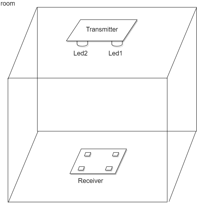 3D view of the system
Why Light?
Light bulbs are everywhere, and the infrastructure for them, power and mounting points, is already in every building. As LEDs replace older bulbs, that infrastructure becomes something more: an LED can be switched on and off millions of times per second, so every lamp can also be a tiny transmitter. This is the idea behind visible light communication (VLC), which is becoming a popular complement to radio based systems.
Indoor navigation is a hard problem. GPS does not work inside buildings, and robots, drones, and people all need to know where they are. Using the lights that are already installed would solve it without any extra infrastructure. Some places where this could help:
- Factories: navigation for autonomous robots. With millimeter accuracy, it could even replace encoders or laser range finders as position feedback.
- Shopping malls: guiding customers through large, confusing buildings, and pushing information such as discounts from nearby shops.
- Museums: location based guides that make visits more interactive.
- Hospitals: guiding wheelchairs and other moving equipment with VLC beacons [1].
- Drones: indoor flight today mostly relies on complex camera systems. VLC could provide a simpler position feedback.
The scope of this project was a simplex (one way) link with modest data rates. High bandwidth VLC, duplex links, networking and MAC protocols, and security were out of scope.
Related Work
VLC positioning systems fall into two groups. Camera based systems decode the light with a phone camera. A neat trick some of them use is the rolling shutter: a CMOS sensor does not capture the whole frame at once, so a modulated light source shows up as stripes in the image, and the stripes encode the data. These systems need a lot of processing, are limited by the camera frame rate, and are hard to make work across many camera models. Photodiode based systems, like mine, are simpler and much faster.
| Work | Year | Modulation | Localization | Accuracy |
|---|---|---|---|---|
| Carrier allocation VLC [2] | 2014 | QPSK | Trilateration | 6 cm |
| Hadamard matrix design [3] | 2017 | OOK | Hadamard matrices | 4 cm |
| Wearables Can Afford [4] | 2015 | Polarization | AoA, camera | sub-meter |
| Rotated environments [5] | 2016 | RSS, least squares | 13 cm (sim.) | |
| Single LED beacon, 3D [6] | 2016 | OOK | RSS and AoA | 7.3 cm |
| LED tracking and ID estimation [7] | 2014 | 4-PPM | Camera | 5.37 cm |
| Visible light and accelerometer [8] | 2014 | OOK | RSS | 25 cm |
| OFDM VLC positioning [9] | 2016 | OFDM | RSS | 4 cm |
| Mobile robot localization [10] | 2016 | Multi freq. | RSS | |
| Investigation of VLC positioning [11] | 2016 | Frequency ID | RSS | 39 cm |
A few ideas from these papers shaped my design:
- Polarization modulation [4]: each light gets a one pixel LCD in front of it that changes the polarization of the light. The receiver has a fixed polarizer and sees the changes, while human eyes cannot perceive polarization at all, so the light looks perfectly steady.
- One LED is enough [6]: combining AoA and RSS with a 3D orientation sensor allows a 3D position from a single LED.
- Orientation matters [5, 8, 12]: a tilted receiver sees a very different signal strength. Modelling the tilt and correcting it with an accelerometer removes much of that error.
- Modulation matters [9]: OFDM gave clearly better positioning accuracy than simple on off keying.
- Frequency per LED [10, 11]: each LED blinks at its own frequency, and the receiver separates them with filters or an FFT and compares the amplitudes.
There are also commercial systems such as Qualcomm Lumicast, Philips indoor positioning, and ByteLight.
System Overview
The system has two sides. The transmitter drives LEDs on and off to send data. Nothing exotic happens to the light itself: data is carried only by the on off waveform. The receiver has 4 photodiodes. Their current is amplified, sampled by the ADC of an STM32F405 microcontroller, and stored in a buffer. The same buffer feeds two pipelines: demodulation, which recovers the LED’s ID and coordinates, and localization, which estimates where the light comes from.
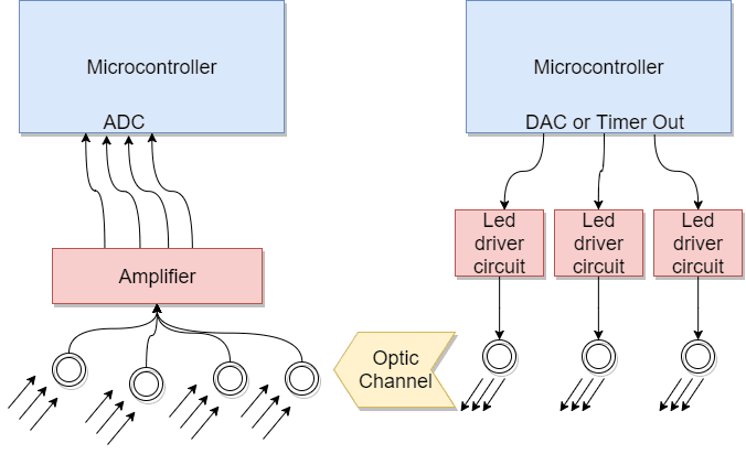 Block diagram of the system
The Receiver
Choosing the Light Sensor
I tested three candidates, all of which respond roughly linearly to light, have a wide viewing angle, and are reasonably fast:
- a photodiode with a transimpedance amplifier,
- a photodiode with a simple resistor,
- a small solar cell.
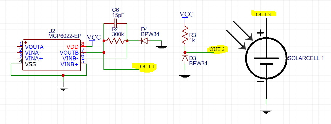 Test circuits for the three receiver candidates
An LED blinking at 1 kHz was pointed at each circuit under different light levels, and I measured the output with an oscilloscope.
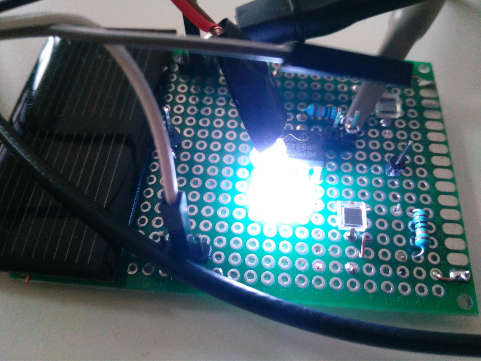 Receiver test setup
| Receiver | Rise time | Fall time | Notes |
|---|---|---|---|
| Photodiode + transimpedance amplifier | 0.9 to 1.1 µs | 0.9 to 1.1 µs | about 0.6 V overshoot |
| Photodiode + 100 kΩ resistor | 10 µs | 10 µs | small signal |
| Solar cell | 100 µs | 300 µs | 0.5 V peak to peak |
The photodiode with a transimpedance amplifier was by far the fastest, and it worked over the widest range of light levels, so I went with it.
The Photodiode: BPW34
The BPW34 is a cheap, easy to find PIN photodiode [13]. Avalanche photodiodes can reach the GHz range, but I did not need more than about 1 MHz. Its important specs:
- Spectral range 430 to 1100 nm: this covers most of the visible band (about 380 to 780 nm).
- Half sensitivity angle ±65°: a wide view angle is important for localization.
- Rise and fall time about 100 ns: this gives a maximum frequency of roughly
$$f_{max} = \frac{1}{t_r + t_f} = \frac{1}{100,\text{ns} + 100,\text{ns}} = 5,\text{MHz}$$
Its current is very linear with illuminance, which makes it a good fit for signal strength based localization.
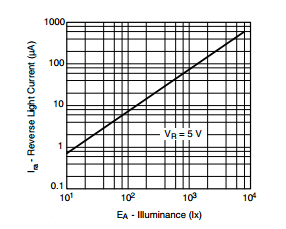
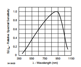 BPW34 photocurrent versus illuminance, and relative spectral sensitivity [13]
The Transimpedance Amplifier
A photodiode produces a current, but the ADC measures a voltage, so a transimpedance amplifier converts one to the other. The gain is set by the feedback resistor. In the first design, I picked it so that 1000 lux, about 100 µA, would give the full 3.3 V range: $R_f = 3.3,\text{V} / 100,\mu\text{A} = 33,\text{k}\Omega$.
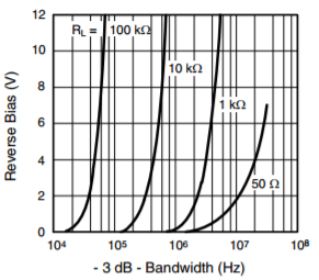 BPW34 bandwidth versus reverse bias voltage [14]
The first prototype had a long settling time and ringing after every edge.
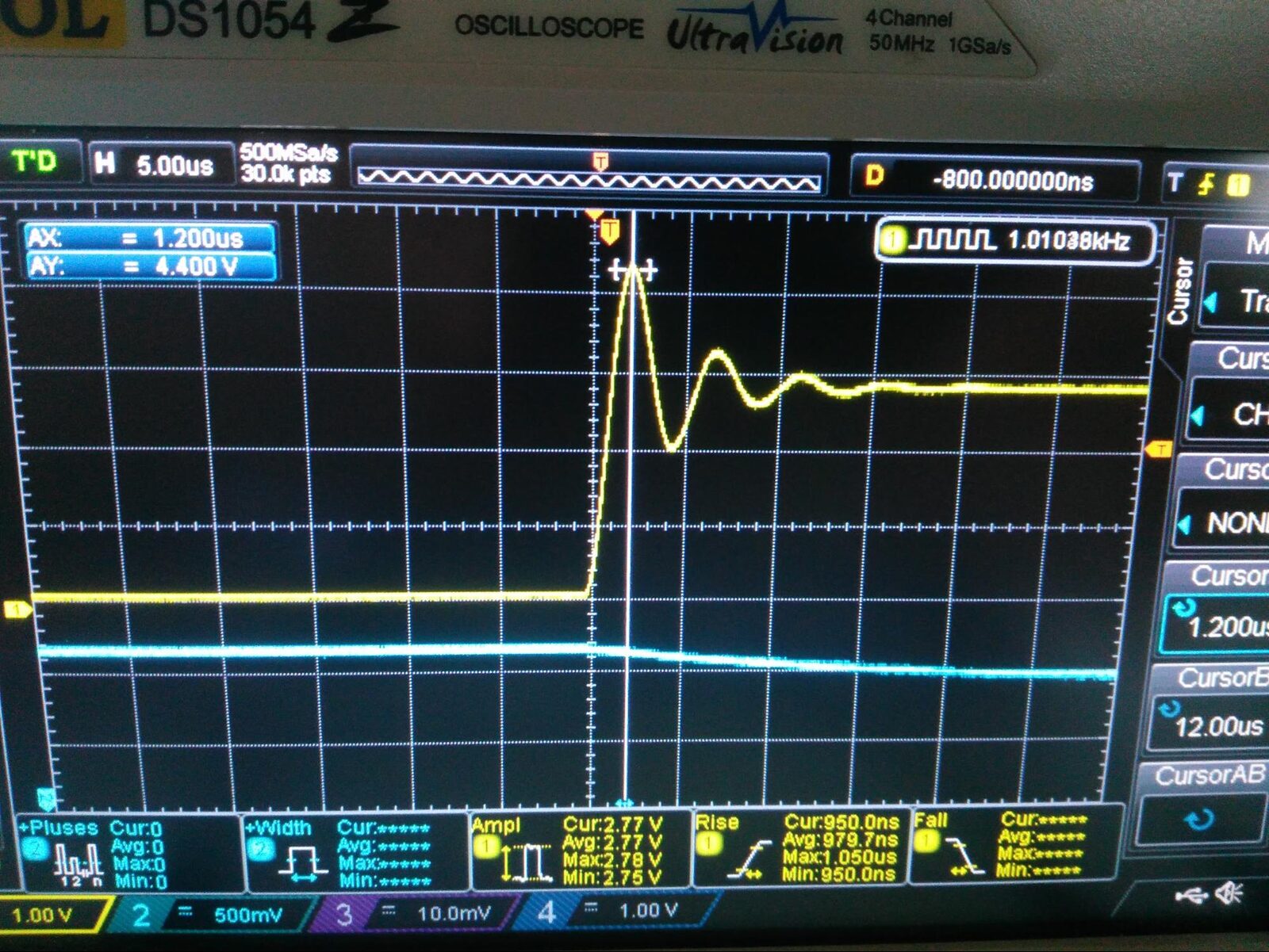 Ringing and long settling time in the first prototype
The reason is that the photodiode’s capacitance at the op amp input makes the circuit unstable unless a small capacitor is placed across the feedback resistor. That capacitor also limits the bandwidth. The highest closed loop bandwidth that still gives a 45° phase margin is [15]:
$$f_{45} = \sqrt{\frac{f_u}{2\pi R_f (C_{in} + C_m + C_d)}}$$
where $f_u$ is the op amp’s unity gain frequency, $R_f$ is the feedback resistor, $C_{in}$ is the photodiode plus board capacitance, and $C_m$ and $C_d$ are the op amp’s common mode and differential input capacitances.
In practice, I did not need high speed. The real challenge was choosing a gain high enough to work in dim light without saturating from other light sources. The final design uses a 40 kΩ feedback resistor and a bandwidth of about 36 kHz. I also replaced the MCP6022 with an OPA4353 [16], which has a 44 MHz unity gain bandwidth, lower noise and distortion, and four amplifiers in one package, exactly one per photodiode. Its only downside is the price. I sampled at 100 kHz, which comfortably covers the signals I used.
The Receiver Board
Localization needs four photodiodes that are exactly aligned, and hand wiring four amplifier circuits was error prone. So I designed a PCB.
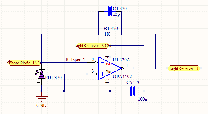 Schematic of one receiver channel
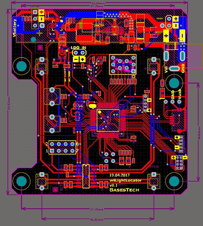 Receiver PCB layout
The board has:
- an STM32F405, chosen for its speed and its floating point unit for DSP,
- the light receiver: an OPA4353 and four BPW34 photodiodes,
- a user interface with LEDs, buttons, and a 7 segment display,
- an MMA8652 accelerometer to measure the board’s orientation,
- a power section with regulators, a battery charger, and battery protection,
- a USB port for power and for streaming data to a computer.
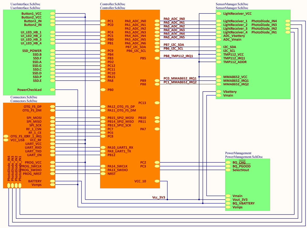 STM32F405 pin assignments, grouped into UI, connectors, controller, sensors,
and power
The photodiode amplifiers go to ADC pins, the accelerometer to I2C, and all data goes to the computer over USB as a virtual serial port. The photodiodes are placed symmetrically so that their relative signal strengths reveal the direction of the light. The battery holder is on the back, and the indicator LEDs and display are on the front, away from the sensors.
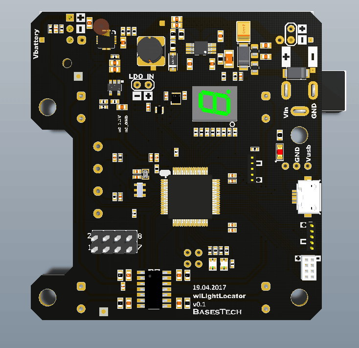
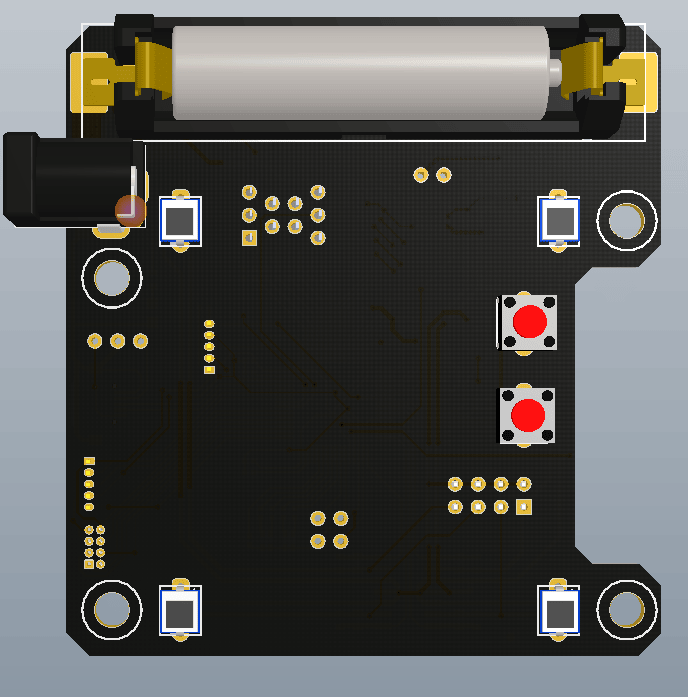 3D model of the receiver board
The STM32F405 runs at 168 MHz, with 48 MHz for USB, 84 MHz for the timers, and 42 MHz for the ADCs.
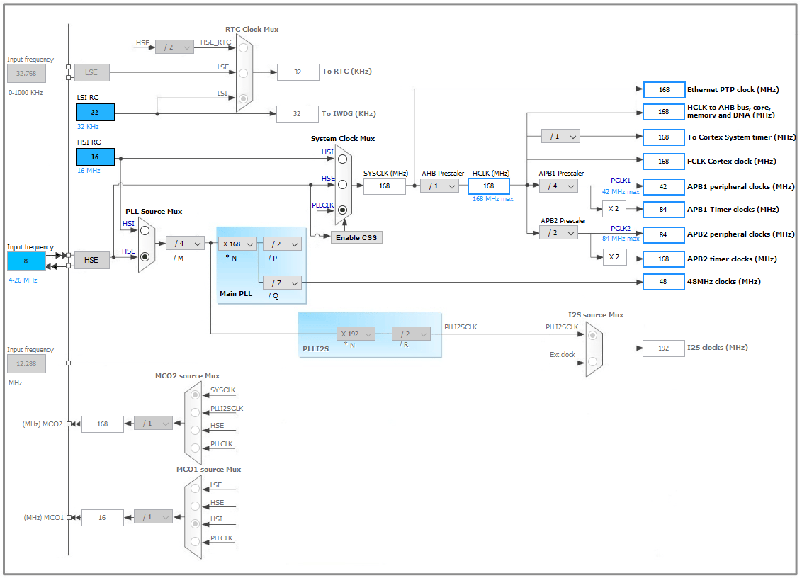 STM32F405 clock configuration
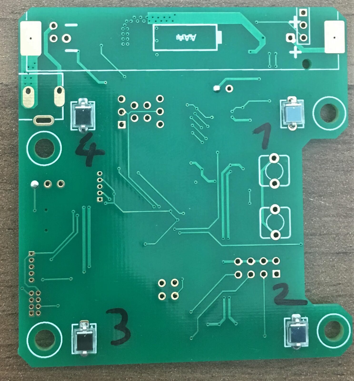
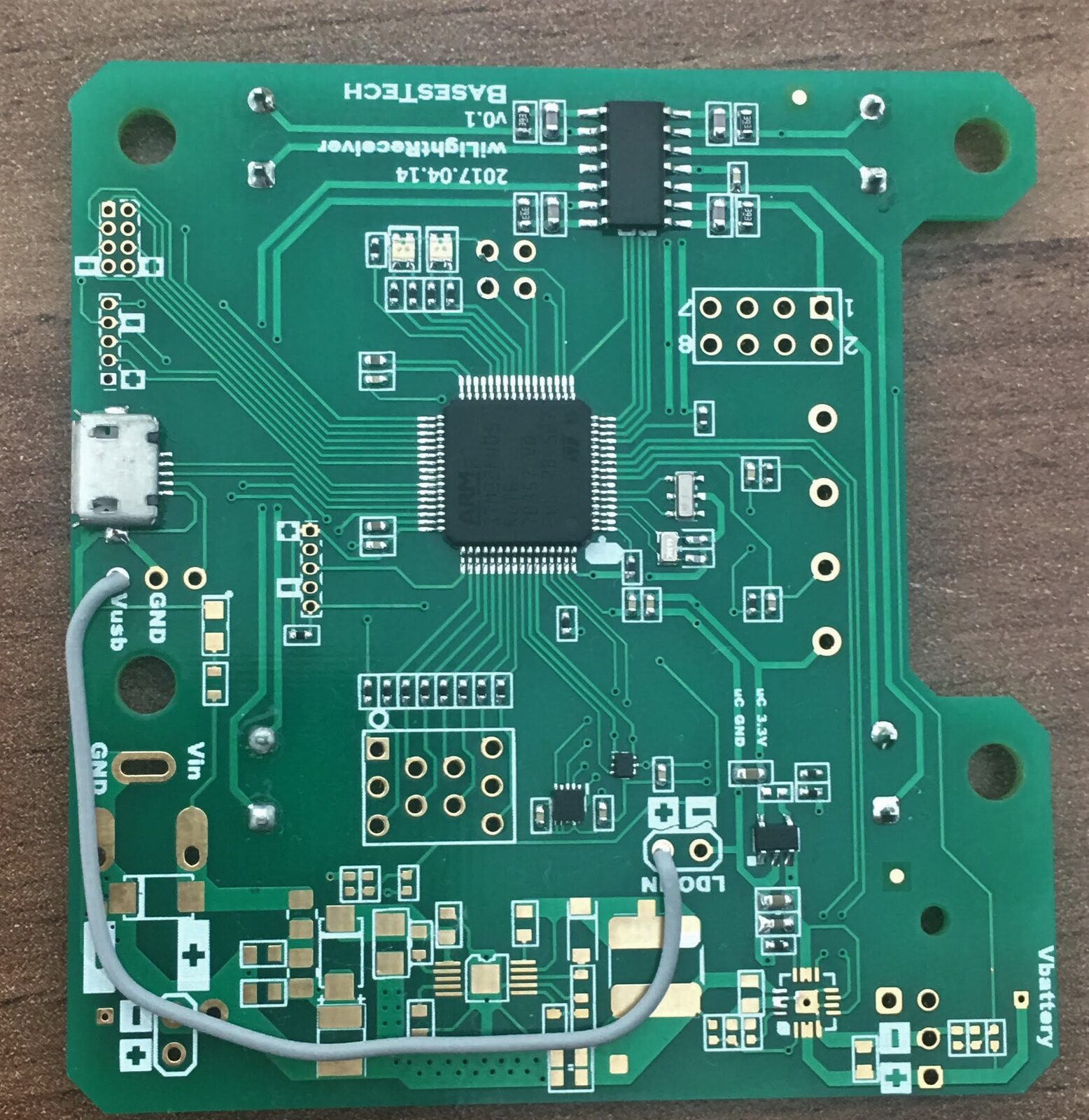 The assembled receiver board
The Transmitter
Early tests used small white LEDs driven straight from microcontroller pins, but localization over a useful range needs much more light. The final transmitter drives 10 W power LEDs at high frequencies.
LED Driver
Power LEDs are usually driven with constant current. My first design was the circuit below, simulated in LTspice. A diode holds the op amp’s positive input at 0.7 V, and the op amp keeps the voltage across a 0.5 Ω sense resistor at the same 0.7 V, so the current is fixed at $I = 0.7,\text{V} / 0.5,\Omega = 1.4,\text{A}$.
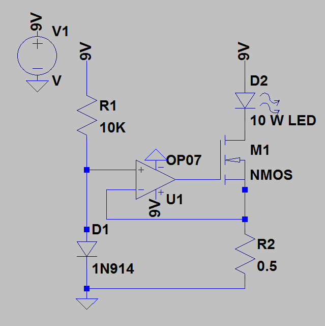 Constant current LED driver design
It worked, but the MOSFET dissipated a lot of power and needed cooling, and the circuit oscillated at around 900 kHz, which would add noise right where my modulation lives. Since LED brightness is also quite linear with drive level, I switched to a simple switch: an IRL510 logic level N-channel MOSFET, driven directly by the microcontroller’s timer outputs.
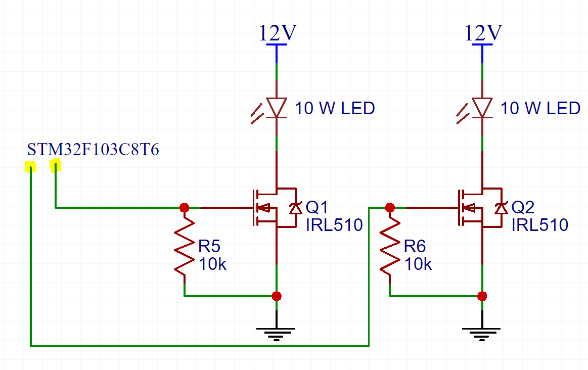 Transmitter schematic
- IRL510 [17]: handles 5.6 A, switches up to about 10 MHz, and has an on resistance of only 0.54 Ω, so it stays cool without a heatsink.
- STM32F103C8T6: the transmitter does not need much computing power, but it needs precise timers to generate the waveforms, which this chip has plenty of. It runs at 32 MHz from an 8 MHz crystal.
- Arduino Due: since LED brightness is fairly linear with current, I also tried waveforms other than square pulses. The Due’s built in DAC made that easy.
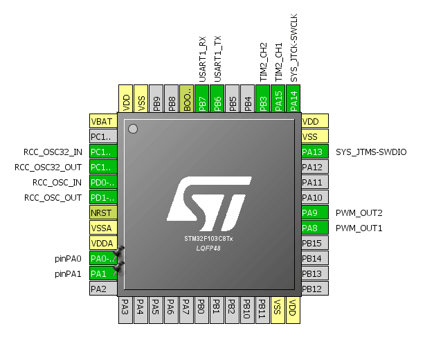 STM32F103 pin assignments
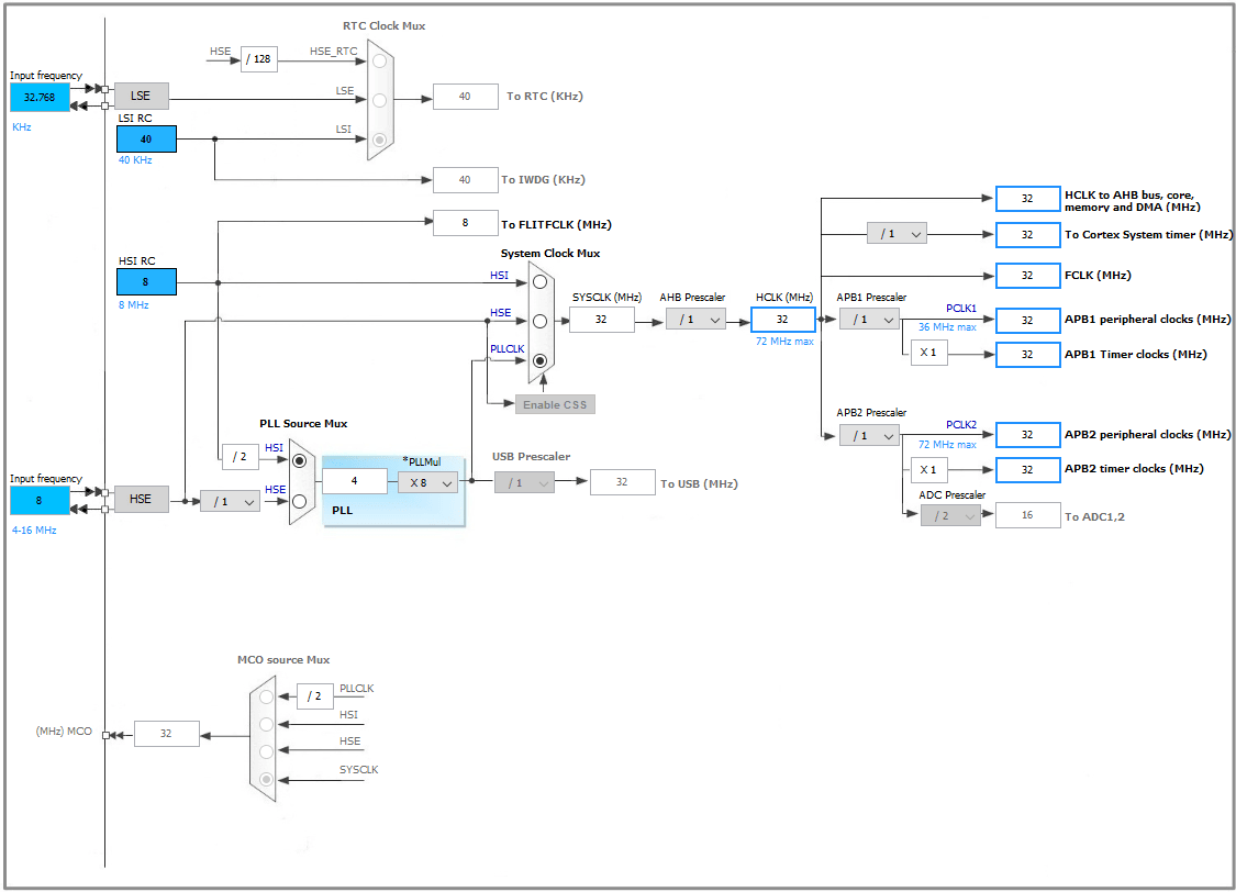 STM32F103 clock configuration
Cooling: with modulation, the LEDs run at about 50% duty cycle, but a 10 W LED still gets hot quickly. Each LED got its own aluminum heatsink.
Transmitter Tests
The transmitter worked cleanly at 1 MHz. I did not test higher, since that is already well beyond what the receiver needs, and the LED itself has more than 10 MHz of bandwidth [18]. One problem showed up: 50 Hz mains ripple on the power supply leaked into the LED waveform. A 220 µF capacitor at the supply input fixed it.
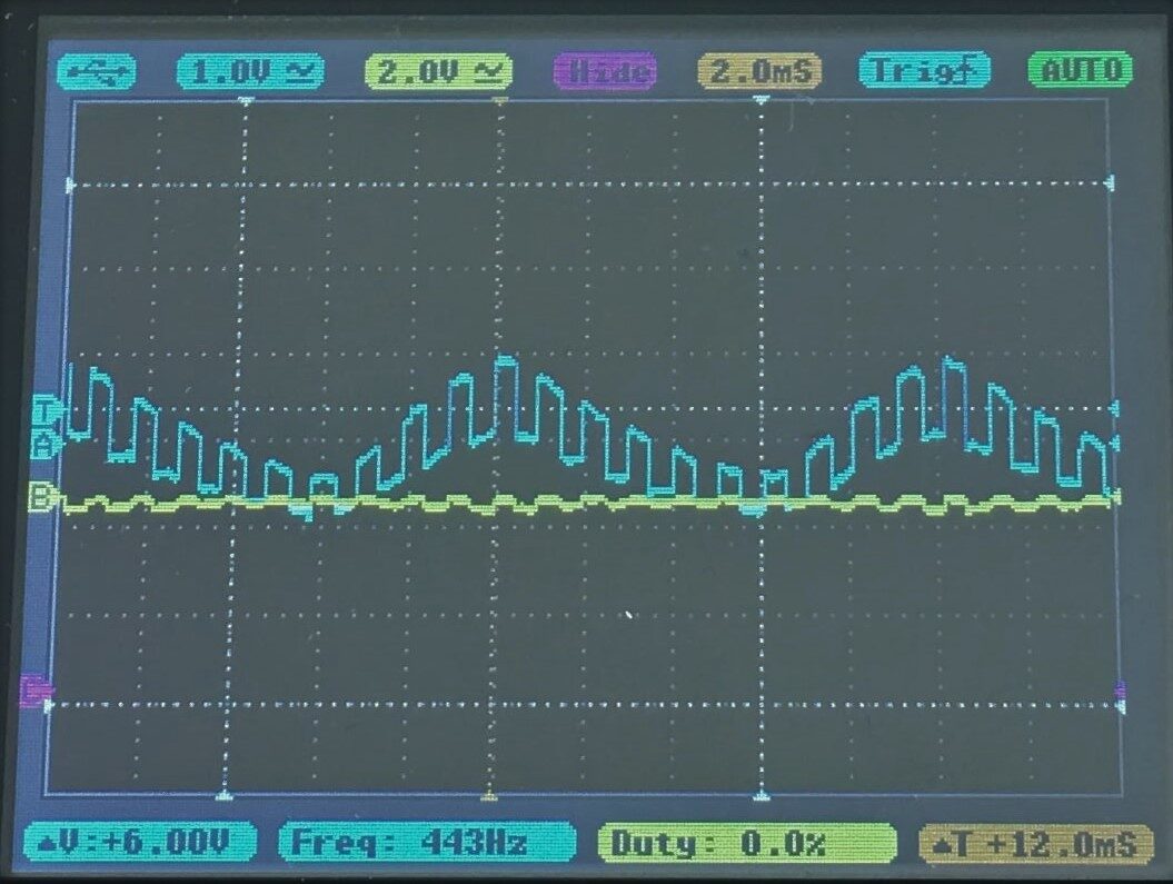
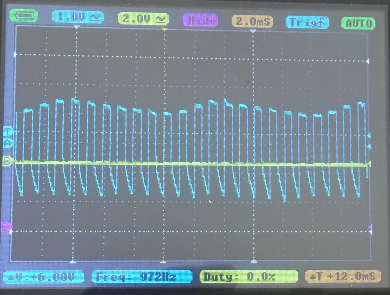 LED waveform before and after adding the supply filter capacitor
Communication
Visible light was chosen precisely so the LEDs can keep lighting the room. That puts two constraints on the modulation: it must not flicker visibly, and it should keep the average light output high.
First Tests with UART
The first link was plain UART: the STM32F103’s hardware UART drove the LED directly, and the oscilloscope’s protocol analyzer decoded the photodiode output. This was a quick way to see how the receiver and transmitter respond to real data before finalizing the design. The link worked up to 115200 baud. I did not test the range at this stage.
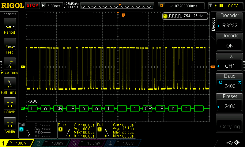 UART over light at 2400 baud
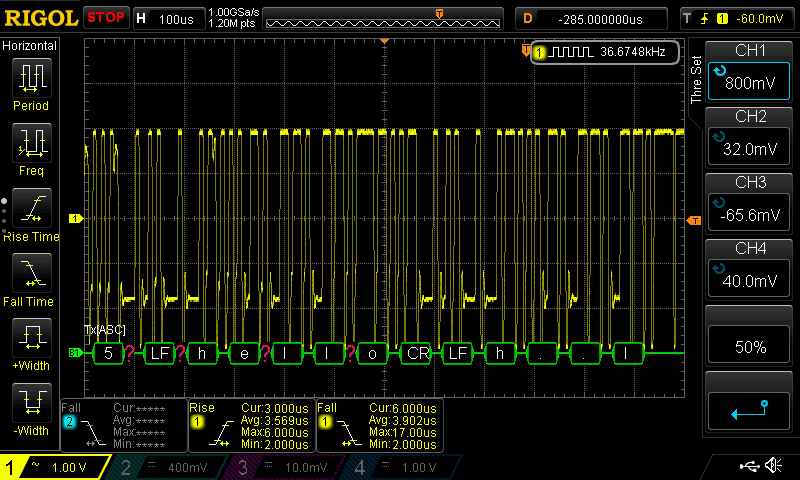 UART over light at 115200 baud
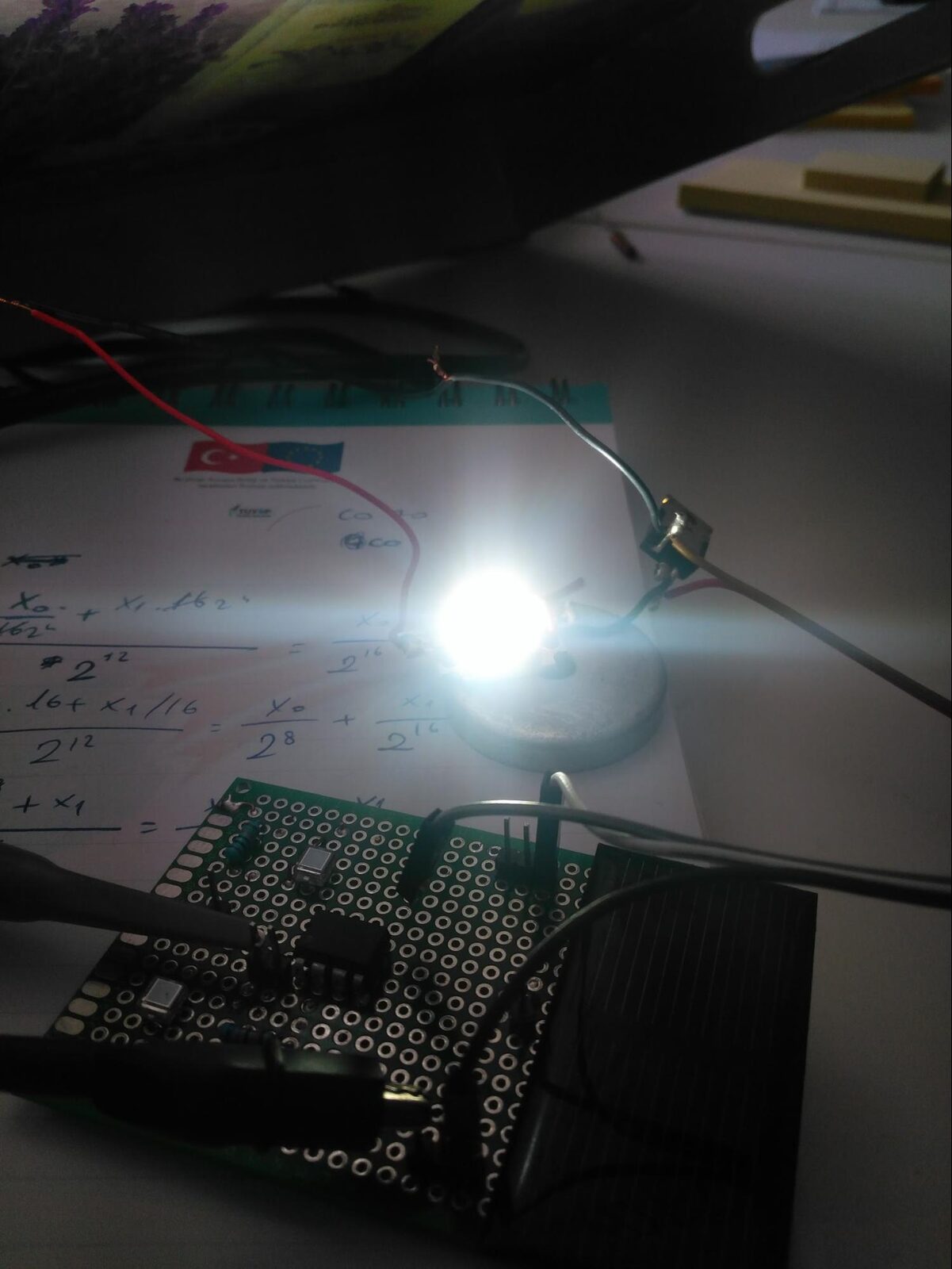 A 10 W white LED switched by an IRL510, running at 25% power
Frequency Shift Keying
With many LED beacons in a room, they need to share the medium. Time division would require all transmitters to be synchronized. With frequency division, each LED gets its own frequencies and they can all transmit at the same time without any shared clock. Working in the frequency domain also removes the DC light level, such as daylight, from the received signal, which helps both decoding and localization. So I chose frequency shift keying (FSK).
Modulator. The STM32F103 uses two timers. Timer 1 ticks once per symbol, and its interrupt loads the next symbol from a buffer. Timer 2 generates the output square wave, and its frequency is set by the current symbol. I started with binary FSK, two frequencies for 0 and 1, and then moved to 16-FSK, where each symbol is one of 16 frequencies and carries 4 bits, which quadruples the data rate.
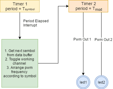 FSK transmitter with two timers
Demodulator. On the receiver, a timer triggers the ADC at a fixed sampling rate, and DMA copies the samples into RAM without involving the CPU. When the buffer is full, an interrupt fires and the CPU processes it while DMA keeps filling the next one.
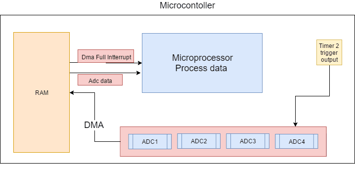 Data acquisition with a timer triggered ADC and DMA
Each buffer is split into the four photodiode channels. An FFT turns each window into a spectrum, a peak detector finds the strongest frequency, and that frequency maps back to a symbol. The same data also feeds the localization pipeline.
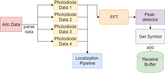 FSK demodulation and localization pipeline
I wrote a small DSP library for this and benchmarked its FFT on a few boards:
| FFT size | Arduino Nano | Arduino Due | STM32F405 (168 MHz) |
|---|---|---|---|
| 16 | 2 ms | ||
| 32 | 6 ms | ||
| 64 | 16 ms | 2 ms | 0.615 ms |
| 128 | 6 ms | 1.215 ms | |
| 256 | 10 ms | 2.549 ms |
The STM32F405 is clearly the fastest of the three.
Pulse Position Modulation
I also implemented a simple 4-PPM link in software. Each 2 bit symbol is sent by placing a pulse in one of four time slots. I inverted the polarity, so the “pulse” is actually a short dark gap and the LED is on about 75% of the time. That keeps the room bright while still sending data.
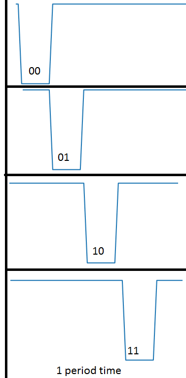 4-PPM symbol coding
Interference
Interference from other light was one of the biggest problems. If any light source saturates the amplifier, nothing else can be received. Making it worse, the BPW34 is most sensitive around 900 nm, in the infrared, where my white LEDs emit almost nothing but sunlight and incandescent bulbs emit a lot. I tried color and polarization filters to make the receiver more selective.
Localization
Angle of Arrival
The first method estimates the direction of the light. To make the four photodiodes more directional, I designed a 3D printed mount that tilts each one outward by 30°. The photodiode facing the light then gets noticeably more signal than the others, and comparing the four gives the angle. With two receivers measuring the angle to the same LED, triangulation gives the position.
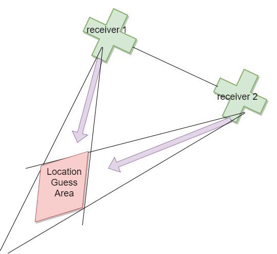 Angle of arrival with two receivers and triangulation
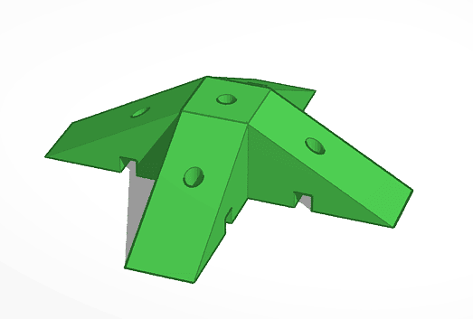 3D printed mount that tilts the photodiodes by 30°
At about 1 m distance, the average angle error was 13.6° in 2D.
Received Signal Strength
The second method estimates the distance to each LED from how bright its signal is. Because I measure the amplitude of the modulated signal, not the total light, the constant background light drops out.
For a Lambertian LED, the channel gain between transmitter and receiver is [10, 11]:
$$G = \frac{(m+1)A}{2\pi d^2}\cos^m(\phi)\cos(\psi)$$
where $A$ is the photodiode area, $d$ is the distance, $\phi$ is the angle at which the light leaves the LED, $\psi$ is the angle at which it hits the receiver, and $m$ is the Lambertian order of the LED. The received power is $P_r = G,P_t$.
For a standard LED, $m = 1$. When the receiver is level and directly below the LED’s plane, both angles satisfy $\cos\phi = \cos\psi = H/d$, where $H$ is the height difference. Substituting and solving for $d$:
$$d = \sqrt[4]{\frac{A H^2 P_t}{\pi P_r}}$$
Since the height is known, the horizontal distance follows from $d_{xy} = \sqrt{d^2 - H^2}$. Each LED sends its own coordinates over VLC, so the receiver ends up with one distance per LED, and solving these circle equations together gives its position. All of this runs on the microcontroller, which streams the coordinates over USB.
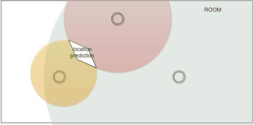 Trilateration from received signal strength
To test it, I divided a 105 cm by 45 cm area at 1 m below the transmitters into a grid, took three measurements in each cell with the receiver level, and averaged the error. The errors range from about 9 to 16 cm, with an average of about 13 cm. Errors grow toward the edges, where the light arrives at steeper angles.
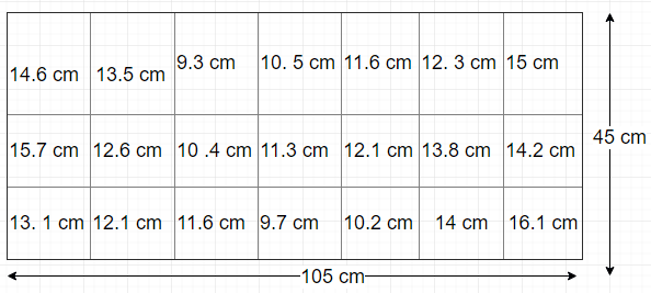 Average position error in each cell of the test grid
Orientation
Both methods assume the receiver is level, and since the photodiodes only see about ±65°, even a small tilt changes the readings. The MMA8652 accelerometer measures that tilt using gravity as a reference. Because the gravity vector always has a magnitude of 1 g, a 3 axis accelerometer gives only two independent angles, pitch and roll; rotation around the vertical axis cannot be measured this way [19].
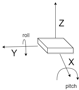 Axes of the receiver
With the rotation order $R_{xyz} = R_x(\phi) R_y(\theta) R_z(\psi)$, gravity $[0, 0, 1]^T$ seen by the accelerometer becomes:
$$\frac{G_p}{\lVert G_p \rVert} = \begin{bmatrix} -\sin\theta \ \cos\theta\sin\phi \ \cos\theta\cos\phi \end{bmatrix}$$
Solving for the roll angle $\phi$ and the pitch angle $\theta$:
$$\tan\phi = \frac{G_{py}}{G_{pz}}, \qquad \tan\theta = \frac{-G_{px}}{\sqrt{G_{py}^2 + G_{pz}^2}}$$
With these angles, the tilt can be compensated in the signal strength model. According to [12], this kind of correction removes 67% to 95% of the error caused by a tilted receiver. I derived and implemented the model, but did not fully test it.
Results
- Receiver: BPW34 photodiodes with an OPA4353 transimpedance amplifier, 40 kΩ gain, and about 36 kHz bandwidth.
- Transmitter: drives three 10 W LEDs at once, tested up to 1 MHz. Square wave FSK comes from the timers, and arbitrary waveforms from the DAC.
- Communication: UART, binary FSK, 16-FSK, and 4-PPM, all modulated and demodulated on microcontrollers.
- Angle of arrival: 13.6° average angle error.
- Received signal strength: about 13 cm average position error.
- Orientation: modelled, but not fully tested.
Conclusion
Visible light is a very promising way to localize indoors. It reuses lighting that is already installed, it can carry data at high rates, it is generally more accurate than radio based positioning, and it updates much faster than camera based systems. That makes it a good fit for real time uses such as controlling robots and drones.
The project touched many areas at once: analog design for the photodiode amplifier, digital signal processing, digital communication, PCB design, and embedded software. That made it complex, but also one of the most instructive things I have built.
Future Work
- Use color filters to cut down interference from other light sources.
- Improve the communication link, since better decoding also improves the signal strength estimates.
- Add a full IMU to compensate the tilted receiver error properly.
- Use more complex modulation and higher frequencies for higher data rates.
- Move parts of the processing into hardware: comparators for thresholding, and an FPGA for the DSP and demodulation, which can run at much higher frequencies than software.
References
- N. U. Hassan, A. Naeem, M. A. Pasha, T. Jadoon, and C. Yuen, “Indoor Positioning Using Visible LED Lights: A Survey,” ACM Computing Surveys, 2015.
- H. S. Kim, D. H. Kwon, S. H. Yang, Y. H. Son, and S. K. Han, “Implementation of real-time indoor positioning system using carrier allocation visible light communication,” 2014.
- J. K. Park, T. G. Woo, M. Kim, and J. T. Kim, “Hadamard Matrix Design for a Low-Cost Indoor Positioning System in Visible Light Communication,” IEEE Photonics Journal, 2017.
- Z. Yang, Z. Wang, J. Zhang, C. Huang, and Q. Zhang, “Wearables Can Afford: Light-weight Indoor Positioning with Visible Light,” in Proc. MobiSys, 2015.
- J. Yan and B. Zhu, “A visible light communication indoor localization algorithm in rotated environments,” 2016.
- Y. Hou, S. Xiao, M. Bi, Y. Xue, W. Pan, and W. Hu, “Single LED Beacon-Based 3-D Indoor Positioning Using Off-the-Shelf Devices,” IEEE Photonics Journal, 2016.
- Y. Nakazawa, H. Makino, K. Nishimori, D. Wakatsuki, and H. Komagata, “LED-tracking and ID-estimation for indoor positioning using visible light communication,” in Proc. IPIN, 2014.
- M. Yasir, S. W. Ho, and B. N. Vellambi, “Indoor Positioning System Using Visible Light and Accelerometer,” Journal of Lightwave Technology, 2014.
- M. Aminikashani, W. Gu, and M. Kavehrad, “Indoor positioning with OFDM Visible Light Communications,” in Proc. IEEE CCNC, 2016.
- H. Sharifi, A. Kumar, F. Alam, and K. M. Arif, “Indoor localization of mobile robot with visible light communication,” 2016.
- Y. C. See, N. M. Noor, and C. Tan, “Investigation of Indoor Positioning System using Visible Light Communication,” 2016.
- E. M. Jeong, S. H. Yang, H. S. Kim, and S. K. Han, “Tilted receiver angle error compensated indoor positioning system based on visible light communication,” Electronics Letters, 2013.
- Vishay, “BPW34 Silicon PIN Photodiode,” datasheet.
- Vishay, “Measurement Techniques,” application note, 2012.
- L. Orozco, “Optimizing Precision Photodiode Sensor Circuit Design,” Analog Devices, 2014.
- Texas Instruments, “OPA353, OPA2353, OPA4353 High-Speed, Single-Supply, Rail-to-Rail Operational Amplifiers,” datasheet.
- Vishay, “IRL510 Power MOSFET,” datasheet, 2011.
- Wayjun Technology, “10W Epistar High Power LED,” datasheet, 2012.
- NXP, “Tilt Sensing Using a Three-Axis Accelerometer,” application note AN3461, 2013.
← [TR] SimpleDSP: FIR filtreleme özelliği eklendi | Internet of Beach →